Carbon-fibre blades for a 5-metre rotor.
A closer look at the original home-workshop project: two 2.5-metre composite blades, one 5-metre rotor, and a proposed 10 kW-class generator.
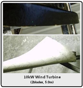
A rotor built in the workshop.
The project centred on a 5 m diameter, two-blade composite rotor intended for a 10 kW, 15-phase axial-flux pancake generator. In the original article, its author suggested roughly 4–5 kW of electrical output for certain operating conditions, based on an assumed 50% generator efficiency and approximately 8–10 kW of mechanical input.
Instead of a moulded commercial blade, the construction started with a welded steel skeleton. Polyurethane foam formed the airfoil shape, followed by fibreglass and a final unidirectional carbon-fibre layer.
Those output figures were predictions, not measured results. In particular, “10 kW” described the generator class; it did not establish that the finished rotor continuously produced 10 kW.
Four stages of a blade build.
Follow the original workshop photographs from bare steel through the finished composite blades. Select any photograph to open the gallery. Use the arrows to browse, or zoom in to inspect the original image.
Start with a steel skeleton.
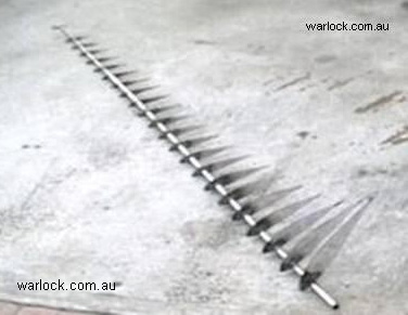
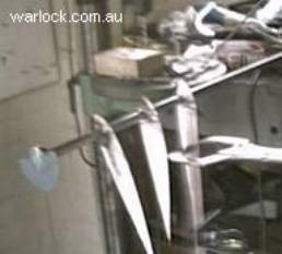
Printed airfoil profiles were transferred to approximately 1 mm steel sheet, cut out and welded along a central steel tube. Each section’s pitch angle was set using a protractor and a plumb line.
Give the blades their shape.
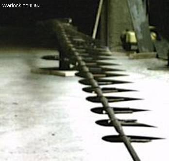
The frame was enclosed and filled with expanding polyurethane foam. The original notes specify approximately 1 kg of Suprasec 5005 and 1 kg of Daltolac GP33. Once cured, the foam was sanded to the changing airfoil profile.
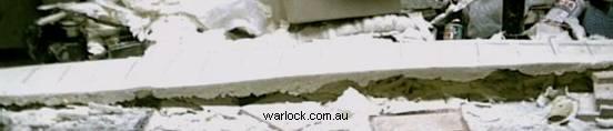
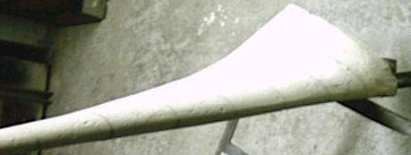
Build up the fibreglass skin.
Vinyl-ester resin went onto the shaped core, followed by chopped-strand fibreglass mat (the record mentions 75 g and 220 g grades). A 400 g biaxial glass-cloth layer was then wrapped around the blade and coated with resin. Sanding and peel-ply formed part of the lay-up process.


Add the carbon-fibre finish.
The outer reinforcement used approximately 197 g unidirectional carbon-fibre cloth. The article then describes more sanding and a vinyl-ester/styrene surface coat before the final smoothing.
The result was a matching pair of 2.5 m blades for the proposed 5 m rotor.
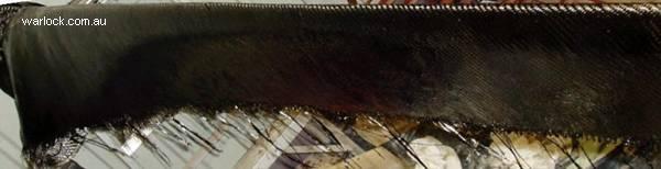
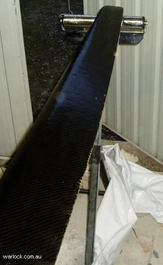

What the original model predicted.
These operating points come directly from the historical article. They have not been recalculated, measured or validated for this new page.
| Parameter | TSR 12.5 | TSR 9 |
|---|---|---|
| Rotor speed | 620.7 RPM | 446.9 RPM |
| Rotational torque | 121.45 N·m | 224.91 N·m |
| Mechanical power (table) | 7,894.3 W | 10,525.7 W |
| Blade efficiency (source) | 0.3 | 0.4 |
| Estimated electrical output (narrative) | 4 kW | 2 kW |
A note on the figures: For TSR 9, the article describes about 4 kW of mechanical input in its text, but the table lists 10,525.7 W. Both values are preserved here; they have not been reconciled.
Original assumptions and data limitations
The original narrative calls TSR 12.5 a better generator match and describes roughly 8 kW mechanical power driving 4 kW electrical output. For TSR 9 it describes 4 kW mechanical power for 2 kW electrical output, while its own numeric table lists 10,525.7 W mechanical power. These statements are inconsistent and are reproduced, not reconciled, here.
No measurements, wind-tunnel validation, generator performance map, blade structural certification or overspeed clearance accompany these historical predictions in this page. Do not treat either operating point as a safe or verified design.
What the materials cost.
The workshop record put blade materials at A$405, or A$1,278 including the generator. These are the original project figures—not present-day supply or manufacturing prices.
| Material | Cost (AUD) |
|---|---|
| Steel | $25 |
| Polyurethane | $40 |
| Glass mat, cloth, resin and MEKP initiator | $220 |
| Carbon fibre (added strength) | $120 |
| Total blade materials | $405 |
- Arc welder, grinder and drill
- Wood saw and sandpaper
- Fibreglass rollers and paint brushes
The author described carbon fibre as an added-strength measure rather than a requirement for that early prototype. That historical judgement is not a structural recommendation for a new blade.
Read the original documents.
Download the original documents for the complete historical record. For newer, exploratory turbine analysis, visit the Darrieus Engineering Notebook.
Adapted for Warlock Apps from the original Warlock Engineering article. Photographs, specifications, reported values and period costs are historical source material, not newly validated results.