Building a 1.8-metre carbon-fibre turbine.
A 2004 workshop story: two custom blades, an improvised generator and lessons from early field testing.
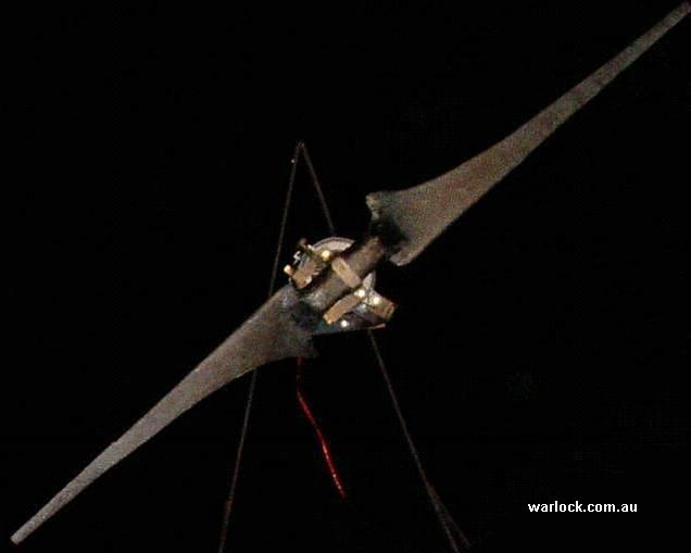
One rotor, two generator ideas.
The project began with a target of 1 kW at 12.5 m/s; the abstract also mentioned 2 kW at 17 m/s. The team designed two light blades around the NACA 2412 airfoil, using the Warlock blade calculator and a target tip-speed ratio of approximately 10.
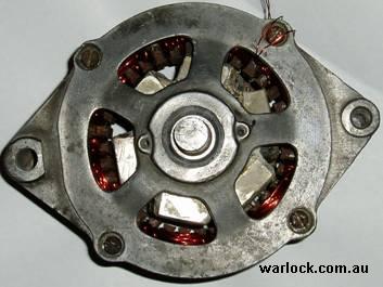
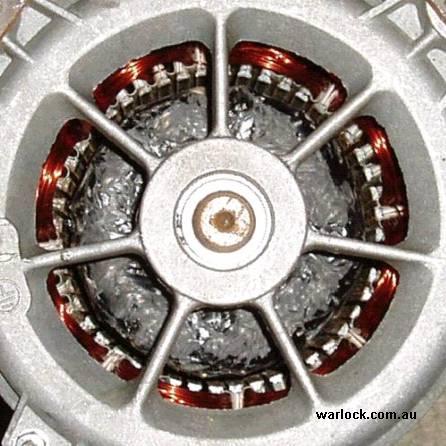
The first generator was a converted 40 A car alternator. When it reportedly produced less than 500 W at the intended blade RPM, the team adapted a ¼ hp induction motor instead, creating an eight-pole, three-phase permanent-magnet generator.
The original text gives conflicting output claims for the converted induction motor: more than 2,000 W in one passage and less than 500 W in another. Both are retained as historical statements; the archive does not provide enough evidence to reconcile them.
From workbench to wind.
Follow thirteen original photographs and charts through generator conversion, blade moulding and field testing. Select any image to enlarge it, then use the arrows or swipe to explore the gallery.
First, build the generator.
The alternator rotor was machined for six angled neodymium magnets, fixed in place with fibreglass and carbon fibre. The workshop added stator shielding to reduce losses. Ultimately, the converted induction motor became the generator for the blade set.
The report describes a 2 mm rotor–stator air gap, three-phase windings measuring approximately 5.6 Ω per phase and 130 V RMS at 1,333 RPM for the converted motor.
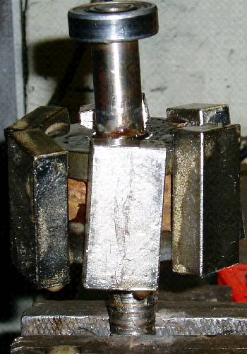
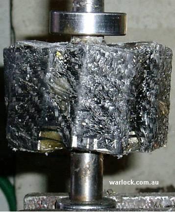
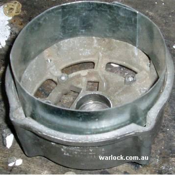
Then, shape the blades.
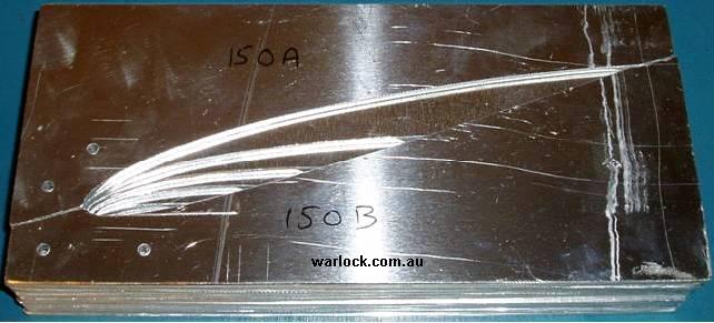
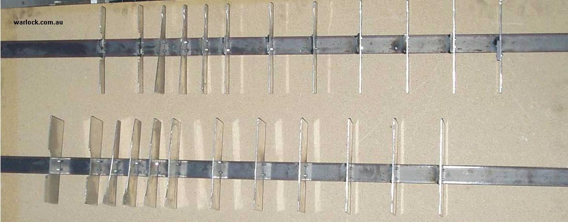
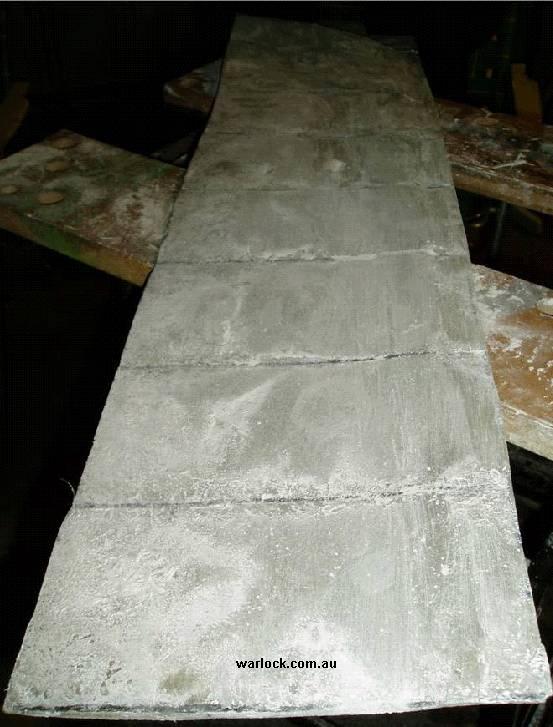
The NACA 2412 sections were cut from 3 mm aluminium sheet and fixed along a steel frame. Aluminium tape and fibreglass formed a surface for the positive moulds; these were refined and used to produce the final negative moulds.
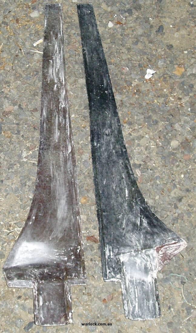
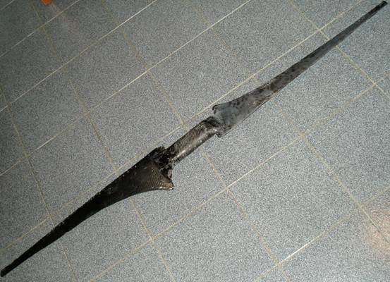
The mould halves were laid up with 220 g chopped-strand fibreglass and vinyl-ester resin, then joined after the resin gelled. The blades were wrapped in carbon fibre, with extra reinforcement around the hub.
Run the field trial.
The turbine was mounted on a trailer and connected to a high-power, multi-tap resistor load. The report says the generator was allowed to reach about 65 V open circuit at 666 RPM before applying the load. Voltage, RPM and tip-speed ratio were recorded.
Important: the original testing method generated turbulent wind, so its author cautioned that the results should be treated as a guide only.
Read the original curves.
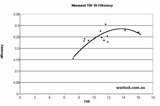
The last two figures show the original efficiency versus tip-speed ratio plot and the reported power versus wind speed trend. They are reproduced as archival charts, not recreated from a new solver.
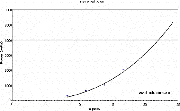
What the field tests showed.
Four wind speeds, five electrical loads and a set of early observations. Open each table to explore the reported readings. A dash means no value was recorded; “stalled” is the original report’s description.
Read the values in context. The abstract reports a 30% peak near TSR 11.6, whereas the conclusion describes a 27% peak over TSR 10–14. Both statements appear in the source. Rotor power was derived from electrical readings and an assumed generator efficiency; it was not a calibrated aerodynamic measurement.
Rotor speed (RPM)
| Wind | 25 Ω | 21.5 Ω | 15 Ω | 10 Ω | 6 Ω |
|---|---|---|---|---|---|
| 30 km/h | 820 | 766 | 809 | — | — |
| 40 km/h | 1302 | 1363 | 851 | 645 | — |
| 50 km/h | 1753 | 1676 | 1489 | 1291 | 1105 |
| 60 km/h | — | 2365 | 2098 | 1744 | 1607 |
Reported power (W)
| Wind | 25 Ω | 21.5 Ω | 15 Ω | 10 Ω | 6 Ω |
|---|---|---|---|---|---|
| 30 km/h | 208 | 205 | 300 | — | — |
| 40 km/h | 524 | 649 | 332 | 252 | — |
| 50 km/h | 950 | 981 | 1017 | 1008 | 940 |
| 60 km/h | — | 1953 | 2019 | 1837 | 1990 |
Blade efficiency (fraction)
| Wind | 25 Ω | 21.5 Ω | 15 Ω | 10 Ω | 6 Ω |
|---|---|---|---|---|---|
| 30 km/h | 0.23 | 0.23 | stalled | — | — |
| 40 km/h | 0.24 | 0.30 | 0.15 | stalled | — |
| 50 km/h | 0.22 | 0.23 | 0.24 | 0.24 | stalled |
| 60 km/h | — | 0.27 | 0.27 | 0.25 | 0.27 |
Tip speed (km/h)
| Wind | 25 Ω | 21.5 Ω | 15 Ω | 10 Ω | 6 Ω |
|---|---|---|---|---|---|
| 30 km/h | 278 | 260 | 275 | — | — |
| 40 km/h | 441 | 463 | 289 | 218 | — |
| 50 km/h | 595 | 569 | 506 | 438 | 375 |
| 60 km/h | — | 803 | 712 | 592 | 546 |
Tip-speed ratio (TSR)
| Wind | 25 Ω | 21.5 Ω | 15 Ω | 10 Ω | 6 Ω |
|---|---|---|---|---|---|
| 30 km/h | 9.2 | 8.7 | 9.2 | — | — |
| 40 km/h | 11.0 | 11.6 | 7.2 | 5.5 | — |
| 50 km/h | 11.9 | 11.4 | 10.1 | 8.8 | 7.5 |
| 60 km/h | — | 16.1 | 14.2 | 11.8 | 10.9 |
Generator-loss estimate and test method
The historical example takes 65 V generated at 666 RPM, subtracts a 48 V battery to obtain a 17 V difference, and uses a 5.6 Ω per-phase resistance to estimate about 3 A per phase, 144 W per phase into the battery and 51.6 W per phase in resistive losses. The report quotes approximately 73.6% generator efficiency for this scenario.
For the resistor-load field test, the report separately states Rₛ = 5.75 Ω for winding plus cable resistance and load resistances of approximately 6.6, 10, 15, 21.5 and 25 Ω. It estimated generated voltage as Vₛ = Vₗ(Rₛ + Rₗ)/Rₗ, then estimated power using Vₛ²/(Rₛ + Rₗ). These are the original author's modelling steps, not an independently verified electrical model.
The build, in 2004 dollars.
The original source recorded a total of A$181 for the two blades, moulds, magnets and the induction motor. This is a historical project cost—not a current materials, manufacturing or retail estimate.
| Component | Cost (AUD) |
|---|---|
| Induction motor | $15 |
| Magnets | $80 |
| Moulds | $72 |
| Two blades | $14 |
| Total | $181 |
Lessons from the workshop.
The team saw potential in higher-speed, more efficient blades: reaching a given power target might need a smaller generator. But rotor–generator matching still required further work. These early observations are not proof of present-day blade strength, speed limits or electrical safety.
Go back to the source.
Both versions of the original article are preserved for comparison, with their historical wording, calculations and photographs intact.
Adapted for Warlock Apps from the original Warlock Engineering project. All 13 figures and period numbers are sourced from the uploaded archive. Formatting and editorial wording have been modernised; no new performance calculations were performed.