From balsa patterns to Kevlar blades.
A hands-on 1.4-metre turbine experiment: design the airfoil, mould a set of composite blades, then take the rotor out for early wind trials.
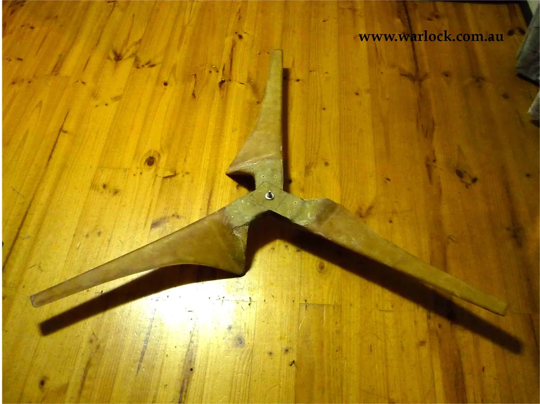
A compact rotor, built to be tested.
The starting point was a 1.4 m rotor with three Kevlar/fibreglass blades, based on an inverse-camber NACA 2412 airfoil. The paper described a nominal 500 W at 12.5 m/s — a design target, not an independently confirmed power rating.
Its abstract suggested around 150 W at 30 km/h, rising to 1 kW at 60 km/h. These were the source’s projected outputs, not readings from a continuous measured power curve. The practical aim was to create repeatable blades and see how they behaved under an electrical load.
That meant working from a balsa airfoil pattern to a plaster form, then to a reusable fibreglass mould before laying up the composite blades. For the wind trials, the workshop used the generator from its earlier 1.8 m turbine experiment.
One pattern. Three moulded blades.
Follow the original workshop through four making stages and nine construction photographs. Three historical performance charts follow in the next section. Select a picture to enlarge it, then use the arrows or swipe to explore all twelve figures.
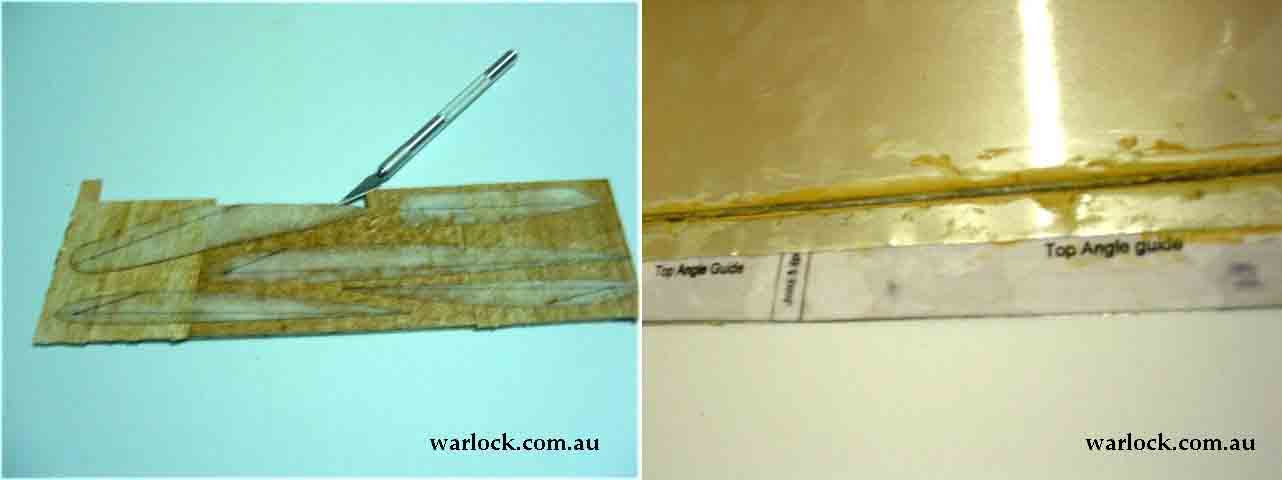
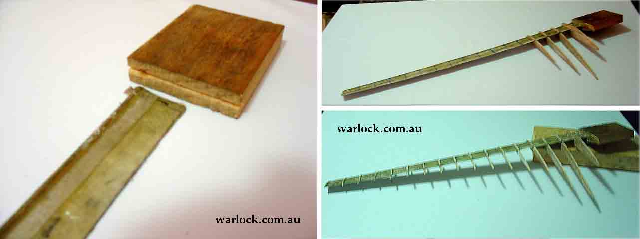
Cut and align the airfoil sections.
Paper airfoil outlines were fixed to balsa and cut into profiles. A sheet-metal angle guide kept the sections aligned, while a 2 mm steel rod guided the root. Together with a wooden hub, the pieces formed the first blade skeleton.
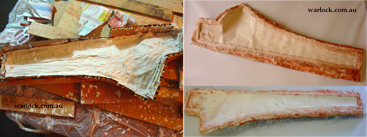
Take a plaster impression.
White gelcoat stiffened the skeleton. A clear plastic skin gave it a smooth surface, sealed at the joints with aluminium tape. Modelling clay formed a retaining wall while plaster and gauze were cast around the pattern in two halves.
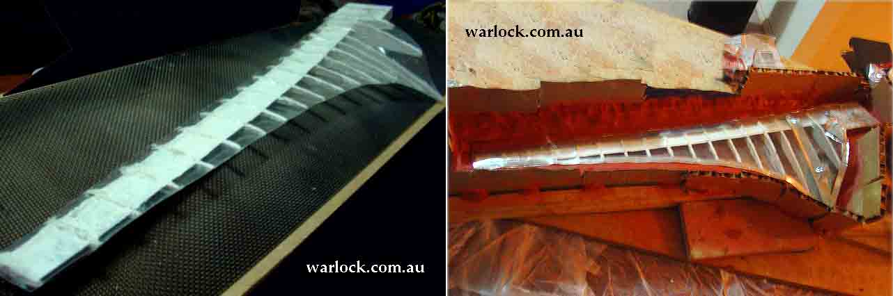
Make the mould reusable.
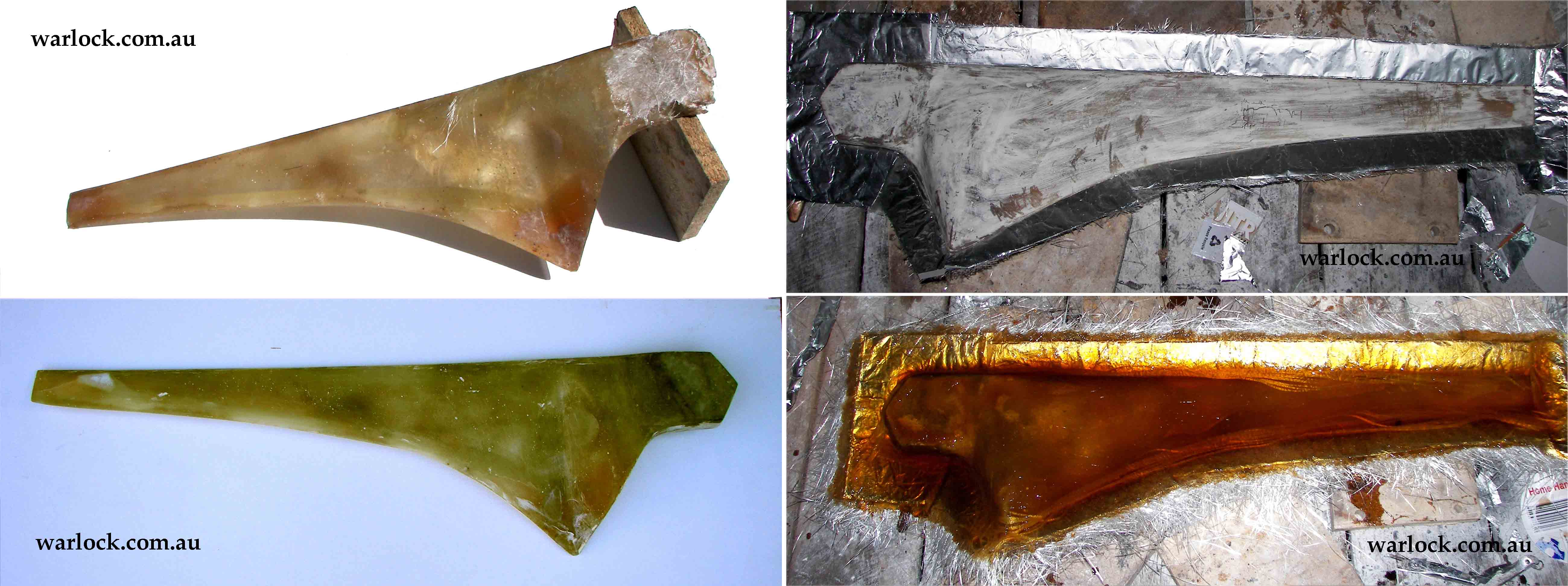
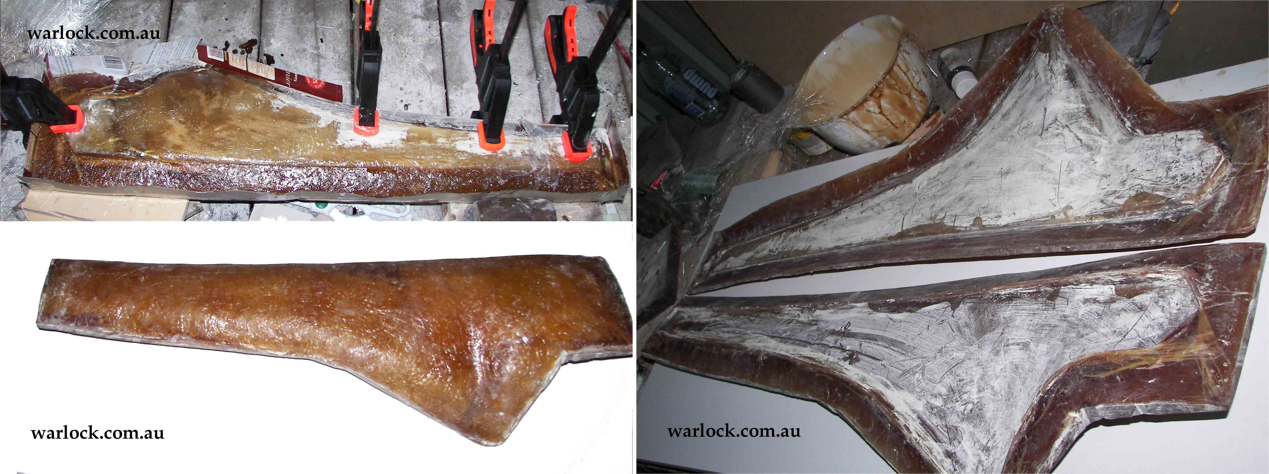
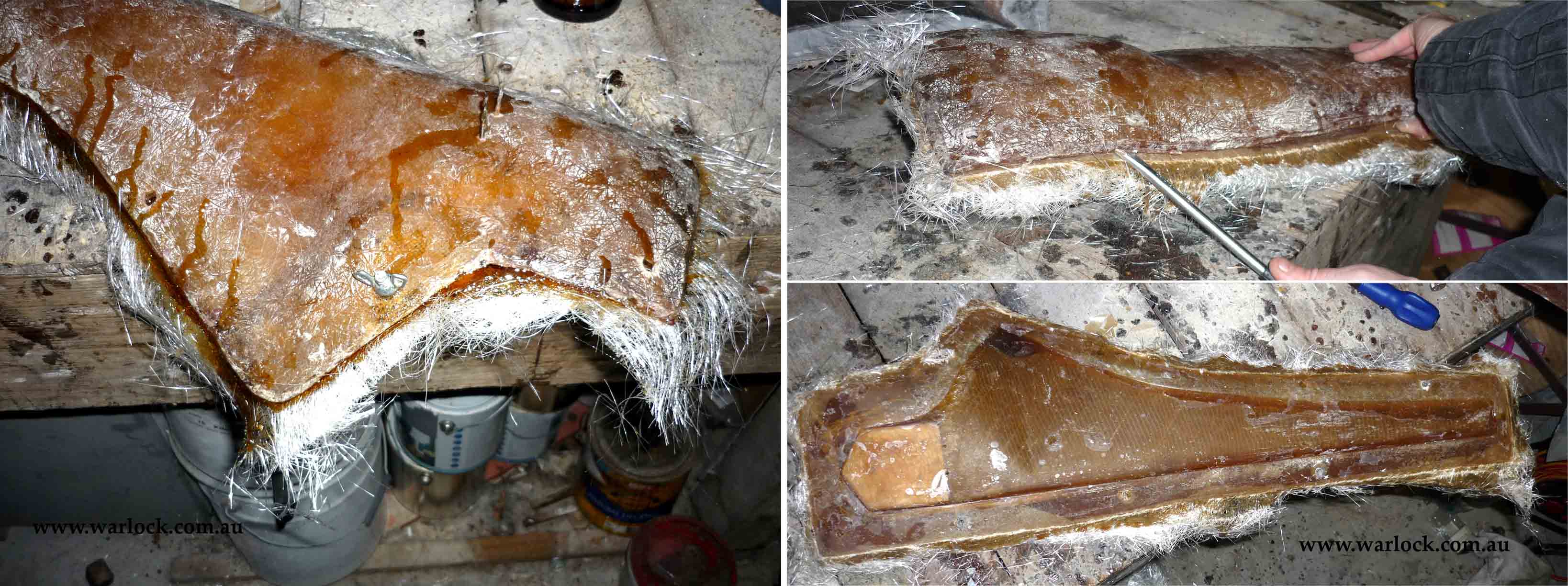
The plaster form was waxed and used to make a positive fibreglass blade. After sanding and adding a triangular wooden hub section, the team formed a stronger negative mould using cardboard, foil, fibreglass and resin. It was trimmed and waxed for further lay-ups.
Lay up, cure and assemble.
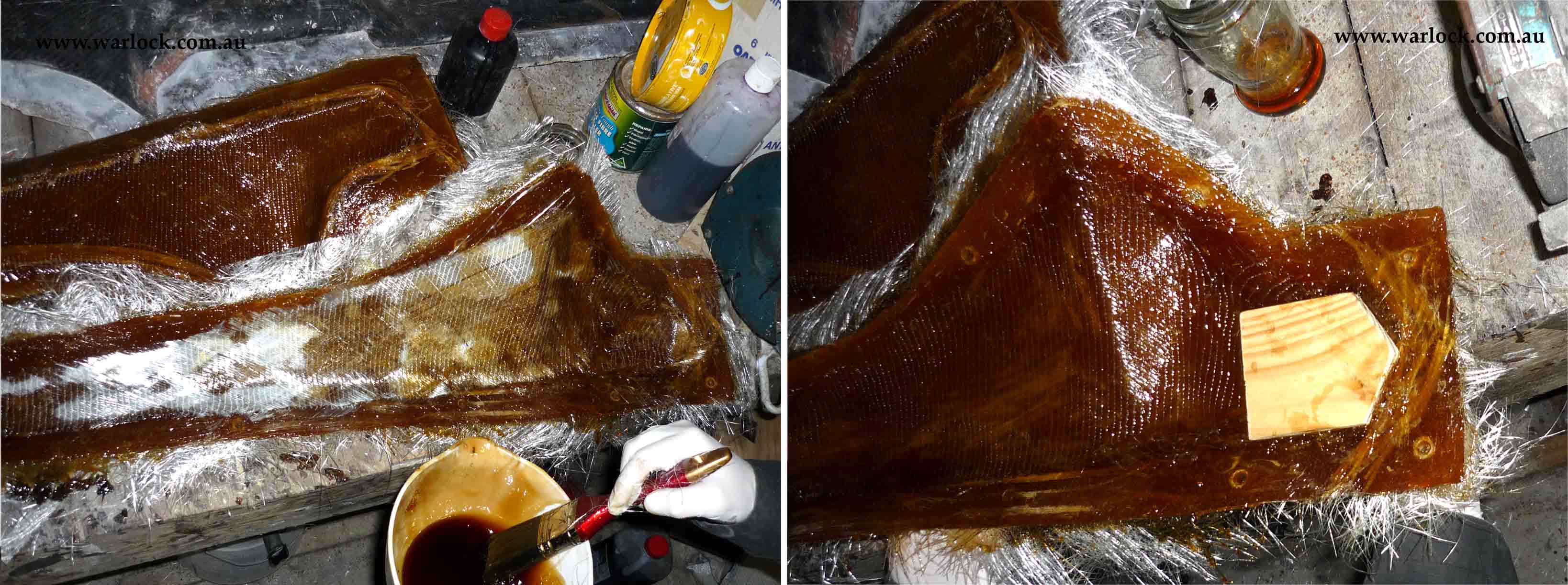
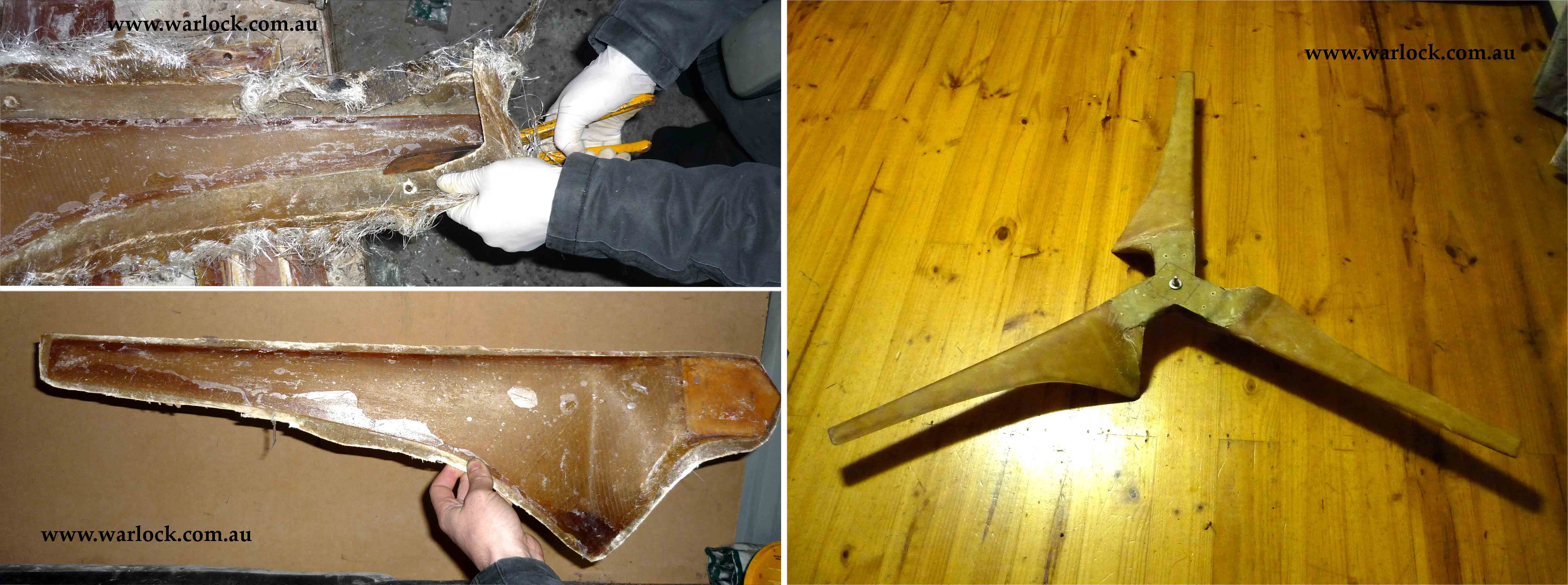
Pre-cut Kevlar and fibreglass went into the mould with resin and a wooden hub insert. The halves were bolted together while the laminate cured. Each blade was released, trimmed and wrapped, before all three were joined and reinforced at the hub.
What did the wind tests show?
The finished rotor was mounted on a trailer and connected to a high-power, multi-tap resistor. Rotor speed and electrical readings were recorded at several loads; the report then estimated blade power using its assumed generator-loss model.
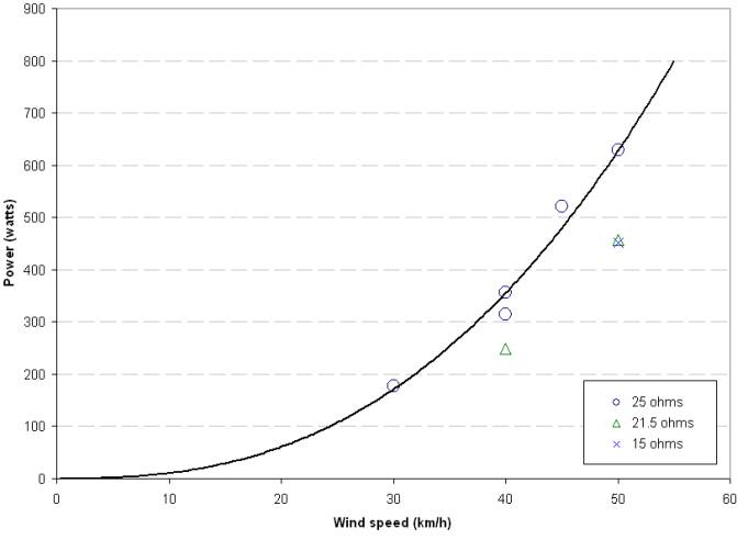
Measured readings versus calculated performance. The original authors noted that the road-test setup produced turbulent airflow. The figures labelled “blade power” were inferred from electrical measurements, rather than measured directly at the rotor shaft. The table reaches 50 km/h; the abstract’s higher output at 60 km/h was not a recorded test point.
The curves behind the numbers.
These three figures reproduce the source report’s plots. Open one to inspect the original axes, loads and data points at a larger scale.
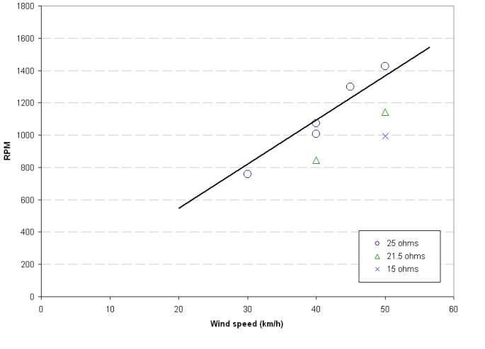
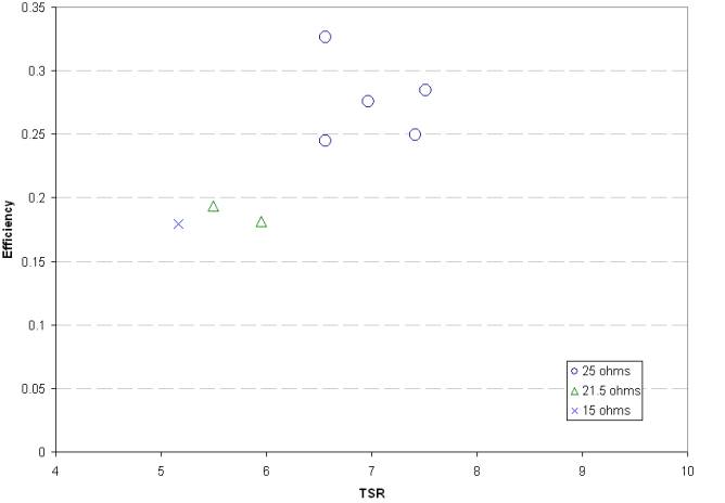
Rotor speed (RPM)
| Wind | 25 Ω | 21.5 Ω | 15 Ω |
|---|---|---|---|
| 30 km/h | 756 | — | — |
| 40 km/h | 1040 | 844 | — |
| 45 km/h | 1299 | — | — |
| 50 km/h | 1425 | 1143 | 2098 |
Calculated blade power (W)
| Wind | 25 Ω | 21.5 Ω | 15 Ω |
|---|---|---|---|
| 30 km/h | 177 | — | — |
| 40 km/h | 335 | 249 | — |
| 45 km/h | 521 | — | — |
| 50 km/h | 628 | 457 | 452 |
Tip-speed ratio (TSR)
| Wind | 25 Ω | 21.5 Ω | 15 Ω |
|---|---|---|---|
| 30 km/h | 6.6 | — | — |
| 40 km/h | 6.8 | 5.5 | — |
| 45 km/h | 7.5 | — | — |
| 50 km/h | 7.4 | 6.0 | 5.2 |
How the original test calculated power
The wind turbine was bolted to a trailer. The generator was allowed to reach an open-circuit reading of 65 V at 666 RPM before a resistor load was connected. The source uses Rₛ = 5.75 Ω for winding and power-cable resistance, with load resistance Rₗ reported as 6.6, 10, 15, 21.5 and 25 Ω.
Its back-calculation is Vₛ = Vₗ × (Rₛ + Rₗ) / Rₗ, then P = Vₛ² / (Rₛ + Rₗ). The report also says blade power was inferred by accounting for generator efficiency. These are the historical author's assumptions and calculations, not independently calibrated aerodynamic or battery-charging measurements.
What the blades cost at the time.
The report lists A$288 in blade and mould-making materials. These are the original Australian-dollar costs, not adjusted for inflation and not a modern quotation.
| Item | Cost (AUD) |
|---|---|
| Balsa, glue, tin sheet | A$10 |
| Gelcoat | A$40 |
| Plastic sheet, plaster | A$25 |
| Modelling clay | A$23 |
| Vinyl-ester resin | A$110 |
| Fibreglass cloth and mat | A$80 |
| Total reported | A$288 |
The value of the experiment.
The workshop produced a repeatable process for moulding three Kevlar/glass blades and a useful set of early wind-test observations. The photographs show the making process; the charts document what was reported. Neither is a substitute for structural testing, modern safety assessment or calibrated performance measurements.
Explore the original report.
The five-page source PDF is available in full, with its original explanations, figures and measurements.
Adapted from the original Warlock Engineering workshop report. All twelve historical source figures, original readings, cost values and supporting PDF remain intact. Wording and presentation have been refined; no new engineering performance calculations were introduced.